|
Cut 3.0D
Software – Features
1. 3D Model Formats
Cut3D includes powerful import
filters that work with most of the industry standard mesh file formats.
3D CAD and Graphics Design
software packages will typically include standard options for saving 3D
models in at least one of the file formats supported by Cut3D. The
commonly used design software products are,
a. Rhino3D
b. 3D Studio
c. AutoCAD
d. Bobcad
e. ProEngineer
f. Solid Works
g. SolidEdge
h. Silo
The internet is
a very useful source for 3D models with many web sites offering 3D
clipart pieces. Many of these also offer Free models that can be used to
test they work with Cut3D.
The 3D file types supported in Cut3D
are
|
STL |
|
STL
Mesh files - binary & ascii |
|
3DS |
|
3D
Studio - binary & ascii |
|
DXF |
|
AutoCAD 3D DXF |
|
OBJ |
|
Wavefront |
|
SBP |
|
ShopBot Digital Probe files |
|
TXT |
|
MaxNC Digital Probe |
|
WRL |
|
VRML |
|
X |
|
DirectX |
|
LWO |
|
LightWave |
|
V3M |
|
Vector Art 3D files |
2.
Sizing and Positioning
3D Models are typically designed
in any orientation and at any size. Cut3D includes options for selecting
what faces of the model to machine, mirroring, rotating and setting the
required size in Inches or Metric.
Multi-sided
Machining
3D models can be machined as
single, double or four sided projects. Simply select the option required
and Cut3D calculates the all of the associated toolpaths automatically!
3. Automatic Boundary detection with Tabs
Automatic Boundary Detection
When cutting 3D
projects it's important to minimize the machining times by not wasting
time cutting unwanted regions of the material. Cut3D includes a unique
option for detecting the model boundaries and limiting the toolpaths
inside these regions.
Interactive
Tab Placement
When cutting models completely
out of the material it's essential to have tabs to stop the job breaking
free during machining.
4. Fast and Efficient 3D Toolpath Options
Roughing
Toolpaths
Fast and efficient Z Level rough
machining removes unwanted stock material quickly and easily, leaving
material on the model for the Finishing toolpath to remove.
Finishing
toolpaths
High quality 3D finishing
cutterpaths are calculated in seconds.
Cut Out
toolpath
Once the model has been machined
to the required size it can easily be cut out of the material using the
Cut Out toolpath. This option automatically calculates the boundary
silhouette and calculates a multiple z level profile toolpath to cut
around the shape.
5. Model Slicing
When a 3D model is to large /
thick to fit under the gantry on your machine or you don't have thick
enough material, the model can very easily be 'sliced' into thinner
sections. For example, a 24" high model can be sliced into 12 x 2" thick
pieces that can then be machined and assembled.
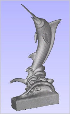
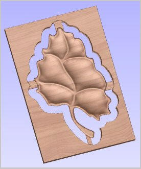
6. Realistic Toolpath Preview
The calculated toolpaths can be
simulated into different materials to show exactly what they will
produce when run on the CNC machine.
7. Estimated machining times
Cut3D automatically calculates
the theoretical cutting times for each of the toolpaths using the
specified feed rates.
8. Saving the toolpaths
Standard postprocessor's are
included for virtually all CNC machine control systems. The
postprocessor's are 'open' and can easily be configured to match
specific file formats.
The
postprocessor supports Automatic Tool Changing and can easily be
modified to save the roughing, finishing and cut out toolpaths into a
single file. |